Weld Neck Flanges
OVERVIEW
Weld Neck Flanges
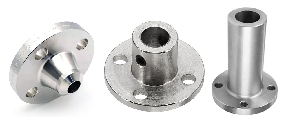
TUBA offer Weld Neck Flanges according to ASME, EN, ISO and DIN standards.Weld Neck Flange is a kind of flange that can relocate stress to the pipes and also ensure decrease in high-stress concentration at its bottom. This kind of flange is chosen for unadorned service circumstances resultant from superior pressure, high or sub-zero temperatures.
A Weld Neck Flanges have an extended tapered hub and steady evolution of wideness in the area of the butt weld connection them to the pipe. Weld Neck Flange are known for preventing turbulence at the joint and reduces corrosion. These types of flanges are highly demanded because of excellent stress distribution through the tapered hub and are easily radiographed for flaw detection.
A weld neck flange consists of a circular fitting with a protruding rim around the circumference. Generally machined from a forging, these flanges are typically butt welded to a pipe. These flanges are also accessible to all our buyers at a very competent price in the leadind market than other firms. These weld neck flange products undergo various destructive and non-destructive methods to check its properties like durability, strength, high tensile, etc.
Weld Neck Flange Specification
| Size Chart | 1/2" (15 NB) to 48" (1200NB) DN10~DN5000 |
|---|---|
| Weld Neck Flange Standards | ANSI/ASME B16.5, B16.47 Series A & B, B16.48, BS4504, BS 10, EN-1092, DIN, ANSI Flanges, ASME Flanges, BS Flanges, DIN Flanges, EN Flanges, GOST Flange, ASME/ANSI B16.5/16.36/16.47A/16.47B, MSS SP44, ISO70051, JISB2220, BS1560-3.1, API7S-15, API7S-43, API605, EN1092 |
| Weld Neck Flange Pressure Rating ANSI | Class 150 LBS, 300 LBS, 600 LBS, 900 LBS, 1500 LBS, 2500 LBS |
| Weld Neck Flanges Pressure Calculation in DIN | 6Bar 10Bar 16Bar 25Bar 40Bar / PN6 PN10 PN16 PN25 PN40, PN64 |
| Weld Neck Flange | 5K, 10 K, 16 K 20 K, 30 K, 40 K, 63 K |
| Weld Neck Flange UNI | 6Bar 10Bar 16Bar 25Bar 40Bar |
| Weld Neck Flange EN | 6Bar 10Bar 16Bar 25Bar 40Bar |
| Coating | Oil Black Paint, Anti-rust Paint, Zinc Plated, Yellow Transparent, Cold and Hot Dip Galvanized |
| Test Certificates | EN 10204/3.1B Raw Materials Certificate 100% Radiography Test Report Third Party Inspection Report, etc |
| Weld Neck Flanges Production technique | Forged, Heat treated and machined |
| Weld Neck Flange Connect Type/ Flange Face Type | Raised Face (RF), Ring Type Joint (RTJ), Flat Face (FF), Large Male-Female (LMF), Lap-Joint Face (LJF), Small Male-Female (SMF), Small Tongue, Large Tongue & Groove, Groove |
| Special design | As per your drawing AS, ANSI, BS, DIN and JIS |
| Weld Neck Flange Test | Direct-reading Spectrograph, Hydrostatic testing machine, X-ray detector, UI trasonic flaw detector, Magnetic particle detector |
| Weld Neck Flanges Equipment | Press machine, Bending machine, Pushing Machine, electric bevelling machine, Sand-blasting machine etc |
| Weld Neck Flange Origin | Indian / West Europe / Japan / USA / Korean |
| Manufacturer of Weld Neck Flange | ANSI DIN, GOST, JIS, UNI, BS, AS2129, AWWA, EN, SABS, NFE etc. B.S: BS4504 , BS3293, BS1560, BS10 The other standard: AWWA C207; EN1092-1, GOST12820, JIS B2220; KS B1503, SABS1123; NFE29203; UNI2276 |
| Weld Neck Flange Uses & application | Bitumen upgraders. Heavy oil refineries. Nuclear power (mostly seamless). Petrochemicals and acids. |
| Weld Neck Plate Flanges Export to | Ireland, Singapore, Indonesia, Ukraine, Saudi & Arabia, Spain, Canada, USA, Brazil, Thailand, Korea, Iran, India, Egypt, Oman, Dubai, Peru, etc |
| Material Test Certificates (MTC) as per EN 10204 3.1 and EN 10204 3.2, Test Certificates certifying NACE MR0103, NACE MR0175 | |
Weld Neck Flanges Materials & Grades
| Materials | : | Standard, Grades |
| Stainless Steel Weld Neck Flanges | : | ASTM A 182, A 240 F 304, 304L, 304H, 316, 316L, 316Ti, 310, 310S, 321, 321H, 317, 347, 347H,904L |
| Carbon Steel Weld Neck Flanges | : | ASTM / ASME A/SA 105 ASTM / ASME A 350 , ASTM A 181 LF 2 / A516 Gr.70 A36, A694 F42, F46, F52, |
| F60, F65, F70 | ||
| Alloy Steel Weld Neck Flanges | : | ASTM / ASME A/SA 182 & A 387 F1, F5, F9, F11, F12, F22, F91 |
| Duplex Steel Weld Neck Flanges | : | ASTM / ASME A/SA 182 F 44, F 45, F51, F 53, F 55, F 60, F 61 |
| 6% Moly / Super Duplex Weld Neck Flanges | : | ASTM / ASME A/SA 182 F 44, F 45, F51, F 53, F 55, F 60, F 61 |
| Low Temperature Steel Weld Neck Flanges | : | ASTM A350 LF2, LF3, LF6 |
| High Yield Weld Neck Flanges | : | ASTM A694 F42, F52, F60, F65, F70 |
| Nickel Alloys Weld Neck Flanges | : | ASTM SB564, SB160, SB472, SB162 – Nickel 200 (UNS No. N02200), Nickel 201 (UNS No. N02201), Monel 400 (UNS No. N04400), Monel 500 (UNS No. N05500), Inconel 800 (UNS No. N08800), Inconel 825 (UNS No. N08825), Inconel 600 (UNS No. N06600), Inconel 625 (UNS No. N06625), Inconel 601 (UNS No. N06601), Hastelloy C 276 (UNS No. N10276), Alloy 20 (UNS No. N08020) |
| Copper Alloys Weld Neck Flanges | : | ASTM SB 61 , SB62 , SB151 , SB152 – UNS No. C 70600 (Cu-Ni 90/10), C 71500 (Cu-Ni 70/30), UNS No. C 10100, 10200, 10300, 10800, 12000, 12200 |
| Alloys Weld Neck Flanges | : | ALLOY 20, ALLOY C, ALLOY C276, ALLOY B2 |
| Other Grade of Weld Neck Flanges | : | Bronze, Brass, Cupro Nickel, Titanium, Inconel, Monel, Hastelloy |
ASME B16.5 Weld Neck Flanges Dimensions:
| ANSI, ASME, ASA, B16.5 150lb/sq.in. WELDING NECK FLANGE RF | |||||||||||
|---|---|---|---|---|---|---|---|---|---|---|---|
| ø | D | b | g | m | a | J* | h | k | Holes | l | Kg. |
| 1/2″ | 88,9 | 11,1 | 34,9 | 30,2 | 21,3 | 15,7 | 47,6 | 60,3 | 4 | 15,9 | 0,500 |
| 3/4″ | 98,4 | 12,7 | 42,9 | 38,1 | 26,7 | 20,8 | 52,4 | 69,8 | 4 | 15,9 | 0,700 |
| 1″ | 107,9 | 14,3 | 50,8 | 49,2 | 33,5 | 26,7 | 55,6 | 79,4 | 4 | 15,9 | 1,100 |
| 1 1/4″ | 117,5 | 15,9 | 63,5 | 58,8 | 42,2 | 35,1 | 57,1 | 88,9 | 4 | 15,9 | 1,500 |
| 1 1/2″ | 127,0 | 17,5 | 73,0 | 65,1 | 48,3 | 40,9 | 61,9 | 98,4 | 4 | 15,9 | 1,800 |
| 2″ | 152,4 | 19,0 | 92,1 | 77,8 | 60,3 | 52,6 | 63,5 | 120,6 | 4 | 19,0 | 2,700 |
| 2 1/2″ | 177,8 | 22,2 | 104,8 | 90,5 | 73,1 | 62,7 | 69,8 | 139,7 | 4 | 19,0 | 4,400 |
| 3″ | 190,5 | 23,8 | 127,0 | 107,9 | 88,9 | 78,0 | 69,8 | 152,4 | 4 | 19,0 | 5,200 |
| 3 1/2″ | 215,9 | 23,8 | 139,7 | 122,2 | 101,6 | 90,2 | 71,4 | 177,8 | 8 | 19,0 | 6,400 |
| 4″ | 228,6 | 23,8 | 157,2 | 134,9 | 114,3 | 102,4 | 76,2 | 190,5 | 8 | 19,0 | 7,500 |
| 5″ | 254,0 | 23,8 | 185,7 | 163,5 | 141,2 | 128,3 | 88,9 | 215,9 | 8 | 22,2 | 9,200 |
| 6″ | 279,4 | 25,4 | 215,9 | 192,1 | 168,4 | 154,2 | 88,9 | 241,3 | 8 | 22,2 | 11,000 |
| 8″ | 342,9 | 28,6 | 269,9 | 246,1 | 219,1 | 202,7 | 101,6 | 298,4 | 8 | 22,2 | 18,300 |
| 10″ | 406,4 | 30,2 | 323,8 | 304,8 | 273,0 | 254,5 | 101,6 | 361,9 | 12 | 25,4 | 25,000 |
| 12″ | 482,6 | 31,7 | 381,0 | 365,1 | 323,8 | 304,8 | 114,3 | 431,8 | 12 | 25,4 | 39,000 |
| 14″ | 533,4 | 34,9 | 412,7 | 400,0 | 355,6 | 336,5 | 127,0 | 476,2 | 12 | 28,6 | 51,000 |
| 16″ | 596,9 | 36,5 | 469,9 | 457,2 | 406,4 | 387,3 | 127,0 | 539,7 | 16 | 28,6 | 60,000 |
| 18″ | 635,0 | 39,7 | 533,4 | 504,8 | 457,2 | 438,1 | 139,7 | 577,8 | 16 | 31,7 | 71,000 |
| 20″ | 698,5 | 42,9 | 584,2 | 558,8 | 508,0 | 488,9 | 144,5 | 635,0 | 20 | 31,7 | 88,000 |
| 22″ | 749,3 | 46,0 | 641,2 | 609,6 | 558,8 | 539,7 | 149,2 | 692,1 | 20 | 34,9 | 102,000 |
| 24″ | 812,8 | 47,6 | 692,1 | 663,6 | 609,6 | 590,5 | 152,4 | 749,3 | 20 | 34,9 | 119,000 |
| * | The data “J” corresponds to the STD schedule | ||||||||||
1. Class 150 flanges except Lap Joint will be furnished with 0.06 (1.6mm) raised face, which is included in ‘Thickness’ (C) and ‘Length through Hub’ (Y1), (Y3).
2. Blind Flanges may be made with the same hub as that used for Slip-on Flanges or without hub.
3. For Slip-on, Threaded, Socket Welding and Lap Joint Flanges, the hubs can be shaped either vertical from base to top or tapered within the limits of 7 degrees.
4. Depth of Socket (D) is covered by ANSI B 16.5 only in sizes through 3 inch, over 3 inch is at the manufacturer’s option.
5. The gasket surface and backside (bearing surface for bolting) are made parallel within 1 degree. To accomplish parallelism, spot facing is carried out according to MSS SP-9, without reducing thickness (C).
6. Welding Neck Flange Bore Size SCH10, SCH20, SCH30, STD, SCH40, SCH60, SCH80, SCH100, SCH 120, SCH140, SCH160, XS
ANSI, ASME, ASA B16.5 300lb/sq.in. WELDING NECK FLANGE RF
| ø | D | b | g | m | a | J* | h | k | Holes | l | Kg. |
| 1/2″ | 95,2 | 14,3 | 34,9 | 38,1 | 21,3 | 15,7 | 52,4 | 66,7 | 4 | 15,9 | 0,900 |
| 3/4″ | 117,5 | 15,9 | 42,9 | 47,6 | 26,7 | 20,8 | 57,1 | 82,5 | 4 | 19,0 | 1,500 |
| 1″ | 123,8 | 17,5 | 50,8 | 54,0 | 33,5 | 26,7 | 61,9 | 88,9 | 4 | 19,0 | 1,900 |
| 1 1/4″ | 133,3 | 19,0 | 63,5 | 63,5 | 42,2 | 35,1 | 65,1 | 98,4 | 4 | 19,0 | 2,600 |
| 1 1/2″ | 155,6 | 20,6 | 73,0 | 69,8 | 48,3 | 40,9 | 68,3 | 114,3 | 4 | 22,2 | 3,300 |
| 2″ | 165,1 | 22,2 | 92,1 | 84,1 | 60,3 | 52,6 | 69,8 | 127,0 | 8 | 19,0 | 3,600 |
| 2 1/2″ | 190,5 | 25,4 | 104,8 | 100,0 | 73,1 | 62,7 | 76,2 | 149,2 | 8 | 22,2 | 5,400 |
| 3″ | 209,5 | 28,6 | 127,0 | 117,5 | 88,9 | 78,0 | 79,4 | 168,3 | 8 | 22,2 | 7,400 |
| 3 1/2″ | 228,6 | 30,2 | 139,7 | 133,3 | 101,6 | 90,2 | 81,0 | 184,1 | 8 | 22,2 | 8,900 |
| 4″ | 254,0 | 31,7 | 157,2 | 146,0 | 114,3 | 102,4 | 85,7 | 200,0 | 8 | 22,2 | 11,900 |
| 5″ | 279,4 | 34,9 | 185,7 | 177,8 | 141,2 | 128,3 | 98,4 | 234,9 | 8 | 22,2 | 16,000 |
| 6″ | 317,5 | 36,5 | 215,9 | 206,4 | 168,4 | 154,2 | 98,4 | 269,9 | 12 | 22,2 | 20,200 |
| 8″ | 381,0 | 41,3 | 269,9 | 260,3 | 219,1 | 202,7 | 111,1 | 330,2 | 12 | 25,4 | 31,000 |
| 10″ | 444,5 | 47,6 | 323,4 | 320,7 | 273,0 | 254,5 | 117,5 | 387,3 | 16 | 28,6 | 44,300 |
| 12″ | 520,7 | 50,8 | 381,0 | 374,6 | 323,8 | 304,8 | 130,2 | 450,8 | 16 | 31,7 | 64,000 |
| 14″ | 584,2 | 54,0 | 412,7 | 425,4 | 355,6 | 336,5 | 142,9 | 514,3 | 20 | 31,7 | 88,000 |
| 16″ | 647,7 | 57,1 | 469,9 | 482,6 | 406,4 | 387,3 | 146,0 | 571,5 | 20 | 34,9 | 113,000 |
| 18″ | 711,2 | 60,3 | 533,4 | 533,4 | 457,2 | 438,1 | 158,7 | 628,6 | 24 | 34,9 | 134,000 |
| 20″ | 774,7 | 63,5 | 584,2 | 587,4 | 508,0 | 488,9 | 161,9 | 685,8 | 24 | 34,9 | 171,000 |
| 22″ | 838,2 | 66,7 | 641,2 | 641,2 | 558,8 | 539,7 | 165,1 | 742,9 | 24 | 41,3 | 195,000 |
| 24″ | 914,4 | 69,8 | 692,1 | 701,7 | 609,6 | 590,5 | 168,3 | 812,8 | 24 | 41,3 | 238,000 |
| * | The data “J” corresponds to the STD schedule | ||||||||||
IMP. NOTES:
1. Class 300 flanges except Lap Joint will be furnished with 0.06 (1.6mm) raised face, which is included in ‘Thickness’ (C) and ‘Length through Hub’ (Y1), (Y3).
2. Blind Flanges may be made with the same hub as that used for Slip-on Flanges or without hub.
3. For Slip-on, Threaded, Socket Welding and Lap Joint Flanges, the hubs can be shaped either vertical from base to top or tapered within the limits of 7 degrees.
4. Depth of Socket (D) is covered by ANSI B 16.5 only in sizes through 3 inch, over 3 inch is at the manufacturer’s option.
5. The gasket surface and backside (bearing surface for bolting) are made parallel within 1 degree. To accomplish parallelism, spot facing is carried out according to MSS SP-9, without reducing thickness (C).
6. Welding Neck Flange Bore Size SCH10, SCH20, SCH30, STD, SCH40, SCH60, SCH80, SCH100, SCH 120, SCH140, SCH160, XS
ANSI/ASME/ASA B16.5 600lb/sq.in. WELDING NECK FLANGE RF
| ø | D | b | g | m | a | J* | h | k | Holes | l | Kg. |
| 1/2″ | 95,2 | 14,3 | 34,9 | 38,1 | 21,3 | 15,7 | 52,4 | 66,7 | 4 | 15,9 | 0,900 |
| 3/4″ | 117,5 | 15,9 | 42,9 | 47,6 | 26,7 | 20,9 | 57,1 | 82,5 | 4 | 19,0 | 1,500 |
| 1″ | 123,8 | 17,5 | 50,8 | 54,0 | 33,5 | 26,7 | 61,9 | 88,9 | 4 | 19,0 | 1,900 |
| 1 1/4″ | 133,3 | 20,6 | 63,5 | 63,5 | 42,2 | 35,0 | 66,7 | 98,4 | 4 | 19,0 | 2,600 |
| 1 1/2″ | 155,6 | 22,2 | 73,0 | 69,8 | 48,3 | 40,9 | 69,8 | 114,3 | 4 | 22,2 | 3,300 |
| 2″ | 165,1 | 25,4 | 92,1 | 84,1 | 60,3 | 52,6 | 73,0 | 127,0 | 8 | 19,0 | 4,700 |
| 2 1/2″ | 190,5 | 28,6 | 104,8 | 100,0 | 73,1 | 62,7 | 79,4 | 149,2 | 8 | 22,2 | 6,500 |
| 3″ | 209,5 | 31,7 | 127,0 | 117,5 | 88,9 | 78,0 | 82,5 | 168,3 | 8 | 22,2 | 8,700 |
| 3 1/2″ | 228,6 | 34,9 | 139,7 | 133,3 | 101,6 | 90,1 | 85,7 | 184,1 | 8 | 25,4 | 11,200 |
| 4″ | 273,0 | 38,1 | 157,2 | 152,4 | 114,3 | 102,4 | 101,6 | 215,9 | 8 | 25,4 | 18,100 |
| 5″ | 330,2 | 44,4 | 185,7 | 188,9 | 141,2 | 128,2 | 114,3 | 266,7 | 8 | 28,6 | 30,500 |
| 6″ | 355,6 | 47,6 | 215,9 | 222,2 | 168,4 | 154,2 | 117,5 | 292,1 | 12 | 28,6 | 36,200 |
| 8″ | 419,1 | 55,6 | 269,9 | 273,0 | 219,1 | 202,7 | 133,3 | 349,2 | 12 | 31,7 | 56,500 |
| 10″ | 508,0 | 63,5 | 323,8 | 342,9 | 273,0 | 254,5 | 152,4 | 431,8 | 16 | 34,9 | 91,000 |
| 12″ | 558,8 | 66,7 | 381,0 | 400,0 | 323,8 | 304,8 | 155,6 | 488,9 | 20 | 34,9 | 105,000 |
| 14″ | 603,2 | 69,8 | 412,7 | 431,8 | 355,6 | * | 165,1 | 527,0 | 20 | 38,1 | 125,000 |
| 16″ | 685,8 | 76,2 | 469,9 | 495,3 | 406,4 | 177,8 | 603,2 | 20 | 41,3 | 178,000 | |
| 18″ | 742,9 | 82,5 | 533,4 | 546,1 | 457,2 | 184,1 | 654,0 | 20 | 44,4 | 261,000 | |
| 20″ | 812,8 | 88,9 | 584,2 | 609,6 | 508,0 | 190,5 | 723,9 | 24 | 44,4 | 268,000 | |
| 22″ | 869,9 | 95,2 | 641,2 | 666,7 | 558,8 | 196,8 | 777,9 | 24 | 47,6 | 328,000 | |
| 24″ | 939,8 | 101,6 | 692,1 | 717,5 | 609,6 | 203,2 | 838,2 | 24 | 50,8 | 380,000 | |
| * | The data “J” corresponds to the STD schedule | ||||||||||
| To be specifiedby customer | |||||||||||
ASME B16.5 Weld Neck Flanges Dimensional Tolerances
| Outside Diameter ≤ 24 = 1.6 mm | > 24 = ± 3.2 mm |
Inside Diameter ≤ 10 = ± 0.8 mm | 12 thru 18 = 1.6 mm | ≥ 20 = + 3.2 mm / – 1.6 mm |
| Diameter of Contact Face 1.6 mm Raised Face = ± 0.8 mm 6.35 mm Raised Face, Tongue & Groove / Male-Female = ± 0.4 mm |
Diameter of Hub at Base ≤ 24 = 1.6 mm | > 24 = ± 3.2 mm |
| Diameter of Hub at Point of Welding ≤ 5 = + 2.4 mm / – 0.8 mm | ≥ 6 = + 4.0 mm / – 0.8 mm |
Drilling Bolt Circle = 1.6 mm | Bolt Hole Spacing = ± 0.8 mm Eccentricity of Bolt Circle with Respect to Facing ≤ 2½ = 0.8 mm max. | ≥ 3 = 1.6 mm max |
| Thickness ≤ 18 = + 3.2 mm / – 0 | ≥ 20 = + 4.8 mm / – 0 |
Length thru Hub ≤ 10 = 1.6 mm | ≥ 12 = ± 3.2 mm |
Manufacturing Standards of Weld Neck Flanges
| ASME/ANSI B16.5 | Weld Neck Flange |
| PRESSURE CLASS | 150 LBS, 300 LBS, 600 LBS, 900 LBS, 1500 LBS, 2500 LBS, DIN Standard ND-6,10, 16, 25, 40 Etc. |
| DIN EN 1092-1 Face Dimensions | PN 2.5, PN 6, PN 10, PN 16, PN 25, PN 40, PN 63, PN 100, PN 160, PN 250, PN 320, PN 400 |
| BS 4504 SEC 3.1, BS 4504[PART 1], BS 1560 BOSS | Weld Neck Hubbed Flange |
| BS10 | Weld Neck Boss Flange |
| TABLE | D, E, F, H |
| DIN FLANGES | DIN 2527, 2566, 2573, 2576, 2641,2642, 2655, 2656, 2627, 2628, 2629, 2631, 2632, 2633, 2634, 2635, 2636, 2637,2638, 2673 |
| PRESSURE CLASS | PN 6 TO PN 100 |
ANSI B16.5 Weld Neck Flange Forms & Availability
| Products | Size | |
| ANSI B16.5 Raised Face Weld Neck Flange | ANSI B16.5 Stainless Steel WNRTJ Flanges | Sizes 1/8″ – 36″ Raised Face or Flat Face |
| ANSI B16.5 Carbon Steel Weld Neck Plate Flange | ANSI B16.5 Alloy Steel Weld Neck Pipe Flange | |
| ANSI B16.5 Weld Neck Raised Face Flange | ANSI B16.5 High Nickel Alloy Weld Neck Flanges | |
| ANSI B16.5 Nickel Class 150 Weld Neck Flanges | ANSI B16.5 Monel Class 300 Weld Neck Flanges | |
| ANSI B16.5 Hastelloy Class 600 Weld Neck Flanges | ANSI B16.5 Titanium Class 900 Weld Neck Flanges | |
| ANSI B16.5 Cu-Ni Class 1500 Weld Neck Flanges | ANSI B16.5 Alloy 20 Class 2500 Weld Neck Flanges | |
| ASME B16.47 SMO 254 Series A Weld Neck Flanges | ASME B16.47 Inconel Series B Weld Neck Flanges | |
Weld Neck Flange Standard
| American Steel Weld Neck Flanges Standard | |
| Standard Code | Standard Name |
| ANSI ASME SA-182 | Weld Neck Flanges |
| ANSI ASME B16.5 | Weld Neck Flange, WNRTJ, WNFF, RFWN Flange |
| ASME – B 16.36 | Weld Neck flange |
| German Steel Weld Neck Flanges Standard | |
| DIN 2573 / 2576 | Flat Flange for Welding (Weld Neck) |
| DIN 2673 | Loose Flanges and Rings for Welding (Weld Neck Flanges and Plain Collars) |
| DIN PN10, PN16 | PN10 Weld Neck Flanges, DIN PN 10 Weld Neck Flanges, PN16 Weld Neck Flange |
| DIN PN20, PN25 | PN20 Weld Neck Flanges, DIN PN 25 Weld Neck Flanges |
| DIN PN40, PN50 | PN40 Weld Neck Flanges, DIN PN 50 Weld Neck Flanges |
| Japanese Steel Weld Neck Flanges Standard | |
| JIS B2220, B2291 | Weld Neck flange |
| JIS 5K, 10K, 30K, 40K, | 5K BLRF Flanges, 10K WNFF Flanges, 30K Weld Neck Flanges, 40K Weld Neck Raised Face Flanges |
| British Standard Weld Neck Flanges Standard | |
| BS 10 Table D | BS 10 Table D Weld Neck Flange |
| BS 10 Table E | BS 10 Table E Weld Neck Flange |
| BS 10 Table F | BS 10 Table F Weld Neck Flange |
| BS 10 Table H | BS 10 Table H Weld Neck Flange |